Resources for Professionals
Instructional Guides for the Tube Removal Specialist

Instructional Guides for the Tube Removal Specialist

This article was written to give guidance on Condenser Tube (Chiller, Condenser, Heat Exchanger, etc.) removal during a demolition project. This process differs from our normal procedure due to the fact that the unit being broken down is not going back into service so care is often considered secondary.Therefore some of our tube removal tools that we offer are not always necessary for projects such as these.
Once it is decided that a unit has reached the end of its life cycle and is due to be replaced it is prudent to review the project in fine detail so that the removal of the unit is done so in a efficient and cost productive manner.
PROCEDURE:
Phase 1: Information gathering
During this walkthrough you will review the work area to learn about the project.There are many factors that you will need to notate before starting this project, what tube removal tools will you need, how many laborers will it require, and so on.Here is a quick list of a few of the most important items:
Phase 2: Tube Removal Plan
During this phase you will review your options for the removal process, should you remove the tubes with the tube sheet intact and pull through the sheet or remove the end sheets and pull the tubes in bunches?The answer to this question can be determined by deciding on how much time you have allotted for this phase, how much effort you are willing to spend, how much space you have in the work area and what kind of manpower you have.It is necessary to review the structural integrity of the unit, once the end sheets are removed the vessel may become weakened and therefore create an unsafe work environment.
Since time is money in today’s environment it is often seen to be the most cost effective way is to remove the end sheet and pull the tubes in bunches, this guide will highlight this process, if you are interested in learning how to pull tubes through the sheet please refer to our article Tube Pulling 101.
Phase 3: Tool List
Now that you have finalized your attack plan you can now start to gather your tube pulling tools for the project.Here is a list of items recommended for the job:
Phase 4: Demolition
Once all plans are finalized and approved and your workforce is trained on process/procedure then it’s now time to get to work.
Process for Removing Tubes Without an End Sheet:
Step 1: Cut Tubes
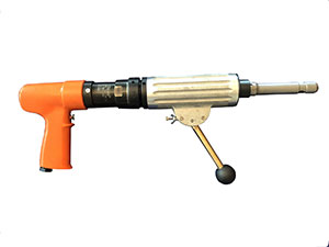
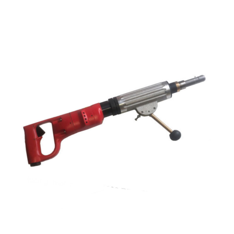
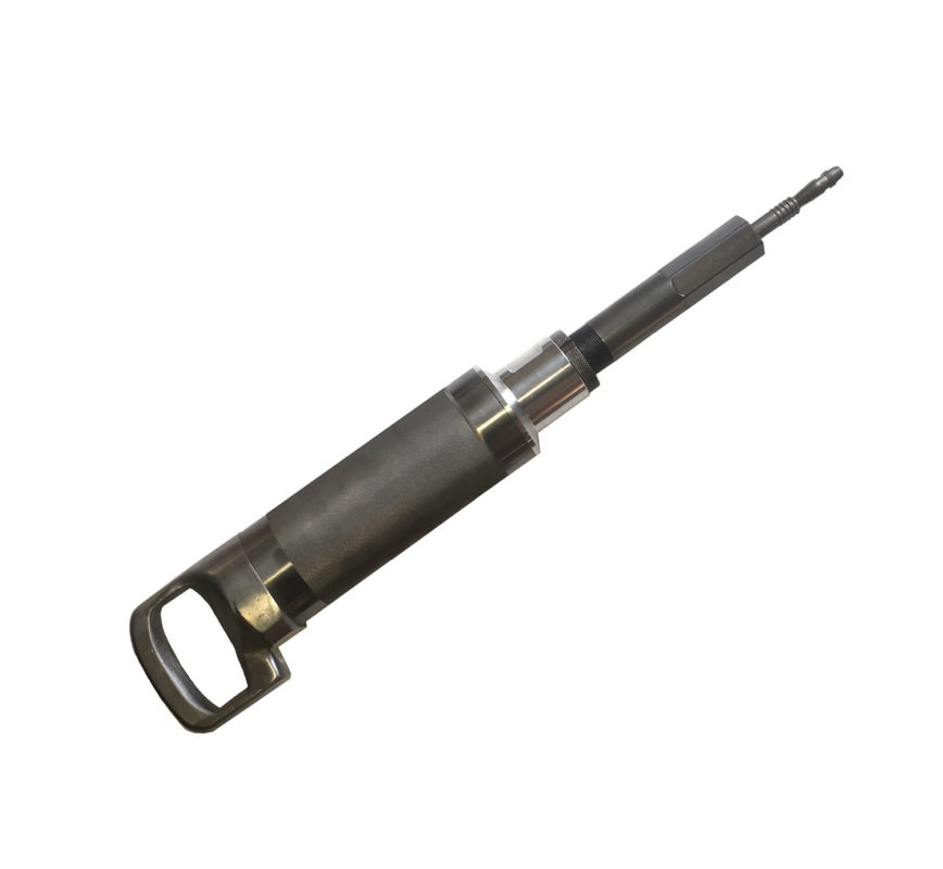
Internally Cut each Tube on both ends, using our AA1 Internal Tube Cutter you to cut up to 20 tubes per minute (depends on tube material and gauge).This will free the tubes from the end sheets allowing for easy removal in STEP 3.
Step 2: End Sheet Removal
Torch cut one of the end sheets (the side that has the most room for removing the scrap tubes), set up chain falls where needed.Recommended to cut the sheet in sections for easier handling and removal.
Step 3: Tube Removal
Now that all the tubes are exposed your crew will have easy access to remove the tubes.In some instances the tubes will be free and simply laying on top of the internal support sheets (or baffle supports) and will move freely.There are times where the tubes are touch rolled into the supports and require a little more effort to be removed.To reduce the wear and tear on your workforce we recommend using our Tube Grippers, which consist of a group of 6 grippers which are then anchored to a anchor plate (more sets equal more tubes per pull).Attaching the Gripper Anchor to a winch will take all the effort out of pulling tubes.Saving you time and money on labor.you will find that pulling tubes on an even plane is critical, it will reduce the binding of the tubes against the support sheets, using a fork lift is key to keeping the pull level.
Step 3: Tube Scrapping/Chopping
Once the process is started the scrap tube is then walked over and fed into the tube chopper.This machine will automatically feed the tube into a rotary blade and chop the tube into 4″ lengths and eject them into a 55 gallon drum or vessel of your choosing.Once this is complete the scrap tubes are then easily removed from the job site and taken to the scrap yard for fulfillment.
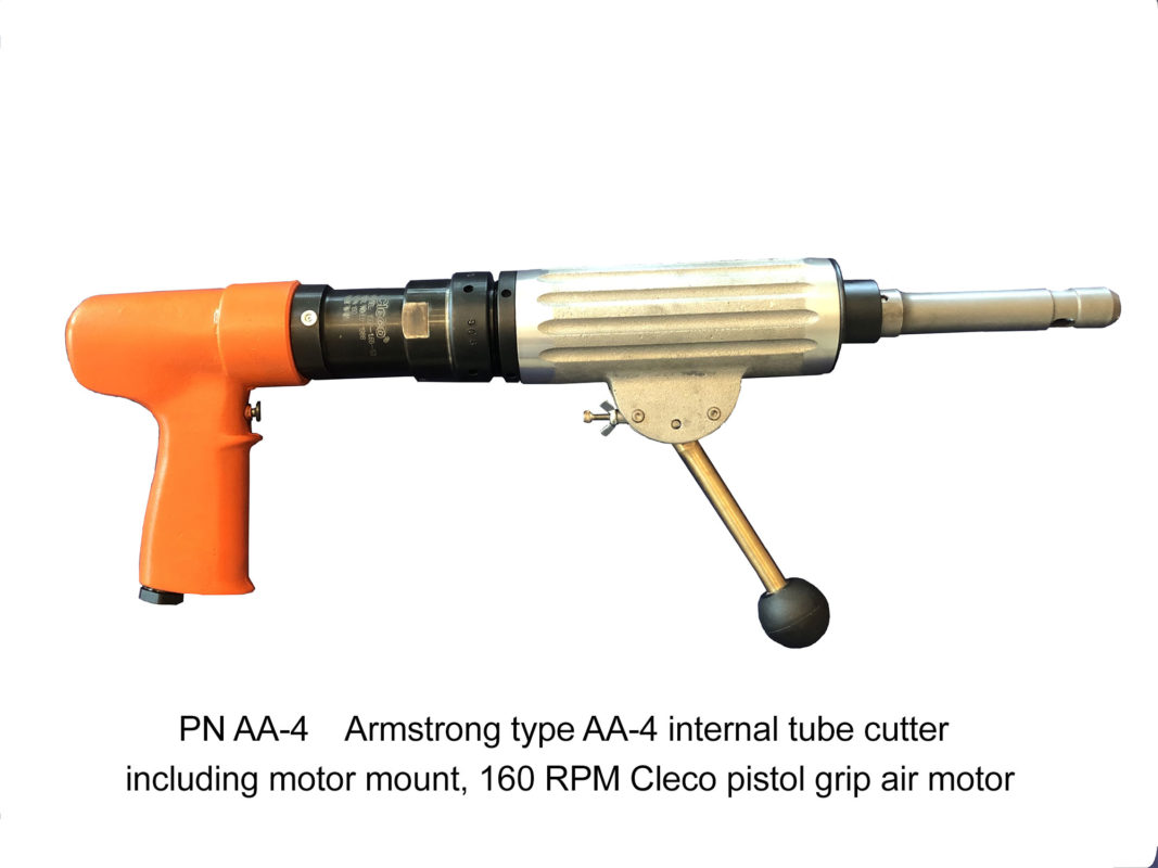
This guide is designed to give you some basic pointers when cutting stainless steel tubes. Cutting stainless is a very time consuming tedious process when compared to cutting softer tubes like Copper or Brass.
Production times vary greatly in comparison, in some cases anywhere from 2-8 tubes a minute can be expected. Using a low speed (160 RPM) cutter is critical when cutting harder exotic materials.
Items you will need:
Step 1: Setting up
As with any project, setup is key to a successful venture. Having the proper tools and knowledge base is very important.
Preparation would include:
We recommend setting the depth of the cut just inside the tube sheet, making sure to be past the sheet is imperative. We suggest this since cutting this harder material creates excessive heat and having the sheet close to the cut will help absorb that heat and prolong the life of each cutting bit.
Step 2: Prepping the tubes
In order to use an internal tube cutter you must be sure to remove all obstacles from the tube, this would include any plugs, built up scale or anything that would inhibit your from inserting the tube cutter.
Step 3: Cutting
Before cutting, confirm what pattern is right for your project, we recommend beginning your cuts in the bottom rows of the sheet and work your way up, unless your job has other needs. When it comes to cutting Stainless Steel it is imperative that plenty of AnchorLube Cutting Fluid is used. A great deal of heat will be generated and this will help prolong the life of your cutting bits. It is key not to force the cutting bit into the tube with any harsh movement, doing so may break the bit before you can even start cutting. Cutting in small steady strokes is important to ensure you get the most life from each cutting blade. Also pulling the cutter out of the tube to remove any cut fragments and reapply cutting lubricant is important and will help improve your productivity. Depending on the tube gauge and size, you will feel the tube break free and in most cases can hear the RPMs on the cutter increase when there is no further resistance. Until you get comfortable with the process it is always a good idea to give a visual check to make sure the tube has been cut completely. In most cases the cut tube will drop slightly so you can easily see it.
What to expect:
This article is written to outline our tube pulling process, it is our hope that it will help you get an idea of how to budget your time during your next retube project. As a rule of thumb we tell our customers to expect at least 250 tubes a day, that is driven by several factors, such as labor force, tube material, unit, etc.
Though that is considered a general estimate, we have routinely experienced instances where we can pulled between 50-100 tubes an hour under normal circumstances. Considering that the tools for the job is exhaustive list it is important to note that Armstrong and Sons will work closely with you to be sure to ascertain the specific items needed for each situation.
Step 1: Information gathering
This step is often overlooked, but it’s very important. Gathering as much information as possible about the unit that is being retubed is critical in the planning of your project. Also keep in mind any required testing and/or classes potential vendors need to attend prior to gaining access to the job sites. The following are some of the key elements needed to gather prior to the project start:
Step 2: Identify what tooling you will need
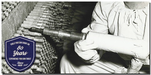
In this step it is helpful to shop around for what tools you will need, in some instances tubes can be removed manually (as much as we hate to admit it). Though this method is very labor intensive and not recommended as it carries a high potential to damage the tube sheet if done carelessly. With 80 years of experience Armstrong and Sons will put you on the right path towards making the best decisions for your project.
Step 3: Prepping the unit/site
Here is where the unit is officially taken offline, drained and heads (if applicable) on both ends are removed.
Step 4: Begin work
Step 5: Cleaning and prepping the tube and support sheet holes
It is very important to clean each hole to ensure a solid seal is made during the last step of the retube. If the sheets have a serration (groove in each hole) then its critical to clean the ring out, typically it can be done using a small pick. We also recommend using a slightly oversized steel brush to remove any additional foreign material (dust, rust etc.)
Step 6 Installing the new tube
This step is rather self explanatory, in this phase you will be inserting the new tube into the vessel. This process can take 2-3 members of the team to complete efficiently. One man positioned on one end of the unit who is responsible for making sure the tube follows the correct line and doesn’t jump into another hole. The next man is on the tube entry side of the vessel at the face of the sheet inserting the new tube while the last man is simply supplying the next tube and helping keep the tube level. It’s easy common for a tube to be inserted on an angle and therefore making it easy to jump tube holes, so keeping it level will help avoid this.
Passing the new tube through each baffle/support sheet can prove to be tricky, slightly spinning the tube will allow the tube to help efficiently find the hole. The man on the opposite side of the unit will becomes key in guiding it’s path through each hole. Tube guilds/pilots are often used in this process to help eliminate any frustration and ultimately speed up the process. They are inserted into the tube ID and removed once the tube is in place.
Step 7 Final installation and rolling
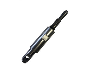
The last step in the tube installation process is known as Tube Rolling, this is where the tube is expanded to create a bond between the new tube and the tube sheet. Prior to rolling, it is important to notate the inlet and return sides on the unit, it is often suggested to have the tubes protrude from the sheet at around 1/8″ or flush against the sheet. The reasoning is to allow better flow for the unit once it is back online. This can be accomplished by precise placement of the tube prior to rolling or once the tube is rolled to use a Trim Stop attachment on our AA series Internal Cutter to trim the excess tube.
Rolling the tube can begin once the tubes are in place and ready as outlined. Please see our Guide for Tube Rolling to help better understand this critical process.
Step 8 Pressure testing
This is the final step in the retube process. The goal here is to ensure that a proper bond now exists between the tube and the sheet. The two most common tests are a Hydro and a Gas test. During this phase the unit is filled with a predetermined amount of pressure and then each end of the unit is closely examined for leaks. If leaks are found, simply make a very slight adjustment to our your Rolling Motor and reroll the leaky tube, being very careful not to overdo it as over rolling tubes can create significant issues with the unit.
Once the team is confident that no leaks are present it is time to complete any remaining tasks outside of the retube and put the unit back into service.
The purpose of tube expanding is to compress the OD (outer dimension) of the tube against a fixed surface (i.e. tube sheet) to create a secure joint or seal.
The wall of the tube must be reduced by a certain percentage based on a few factors, most importantly is the tube material, the basic rule of thumb is that the harder the material the less of a crush is required.
The following are tools/items you will need for this project:
The process can be very cumbersome and to some, very intimidating, since if a tube is over rolled it runs the risk of failing sooner then later. Carefully following these steps will ensure a successful project outcome:
Step 1: Most critical – Get your measurements from 5 random locations (helps create a better random number)
Step 2: Calculate your measurements to find your target crush number (in thousandths)
STEP | TUBE # | Example | 1 | 2 | 3 | 4 | 5 |
A | Tube Sheet Hole | .760” |
|
|
|
|
|
B | -Tube O.D. | .750″ |
|
|
|
|
|
C | =Clearance | .010″ |
|
|
|
|
|
D | + Tube 1. D. | .620″ |
|
|
|
|
|
E | + 5% Reduction | .006″ |
|
|
|
|
|
F | Finished 1. D. | .636″ |
|
|
|
|
|
Step 3: Positioning the tubes
Not a critical step but common practice is to place your tube on the inlet side of the unit with 1/8’’ protruding from the sheet. Uniform placement of tubes will have an impact on flow. If the tubes are longer and projecting farther then desired we provide tube trimming accessories with our line of internal tube cutters.
Step 5: Setup your expander
Be careful not to roll inside the sheet, doing so will weaken the wall of the tube and drastically reduce the life of the tube. Recommended depth is to roll the tube within 75% of the sheet.
Step 6: Setting up your Rolling Motor
To set your rolling motors torque setting begin with the lowest setting to ease yourself into the process, take note that when rolling harder material such as stainless steel and titanium that the process should be done quickly because these materials have a greater tendency to work harden; therefore minimal or no rerolling should be attempted. The Airtoole 720 rolling motor allows for an easy adjustment and then locked into place once the designed torque is reached.
After each pass, measure the ID of the now rolled tube to see how close you are to your premeasured target. Once the target ID is reached, lock in your RM torque setting and begin rolling the row of tubes.
Note: When inserting the expander into the tube you must make sure not to push the tube into the sheet. It is easy to tap a tube into the sheet and then begin rolling without knowing that the position of the tube has changed.
What happens if: The tube is undersized and spins as you begin rolling it. An easy way to overcome this problem is to lightly secure the other end of the tube with a pair of vise grips to keep it from spinning.
Step 7: Leak testing
Once all the tubes of both the inlet and outlet have been successfully rolled it is now time to ensure that a proper joint has been accomplished. Depending on the system and available options leak test can be done in various ways. Hydro tests are very common but can lack the amount of pressure needed to make sure that no leaks are present.
Pro tips:
Use of Loctite – Loctite provides an extra level of security in making sure your tubes are securely in place and free of any leaks.
Single pass vs. multi pass systems – depending on the system it is a good idea to note whether the system it is a single or multi pass system. This will come into play when setting the desired tube location (within 1/8” from the sheet on the inlet side.
Production – you can expect to roll 600-800 rolls a day depending on material and which roller you choose from.
Tube material Guide:
Knowing how to determine wall reduction is important, however it is equally important to know the characterisitics of the popular tubing material. You should know the proper wall reduction in which would apply to each material. A rule of thumb is the harder the material the less wall reduction is required to obtain the proper joint. The following are recommendations for the amount of crush that should be applied to different material types.
Copper and Cupro Nickel: 8-10%
Steel, Carbon Steet and Admiralty Brass – 7-8%
Stainless steel and titanium – 4-5%
Here are some often used terms:
Under rolling – when a tube is not rolled to your specifications, in most cases the tube will not create a bond that you are looking for.
Over Rolling – Is when a tube is expanded beyond your intended target ID. Over rolling can do considerable damage to a vessel. Over rolling will decrease the dimensions fo the ligament between tubes and weaken the bridge. Once a ligament is weakened it will cause a reaction in all ligaments surrounding that weak ligament. If we descrease the strneth of the ligament the tube next to the tube being rolled will leak.
Over rolling will also cause distortion in the tube sheet, producing egg shaped holes. Over rolling has been known to cause a tube sheet to bow or warp to the point where the standard length of the tube coul not be used in a vessel until the bowing or warpage is returned to normal.
Improper preparation of tube sheet holes: Can cause tubes to leak, the tube sheet is gouged it is more difficult to expand a tube to fill these gouges or tears without over rolling. The smoother the tube sheet hoel the easier the roll.